04-22-2018, 03:13 AM
I've taken a few different approaches for packaging and using the controller, and thought it was about time to share.
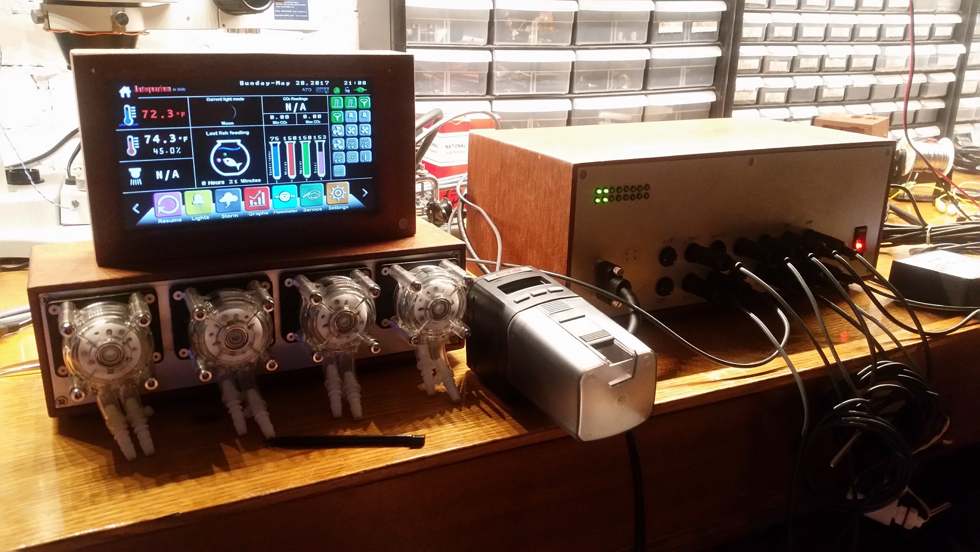
This is how I've set up my devices. I made mahogany and aluminium boxes, and moved everything to a single, self-contained case.
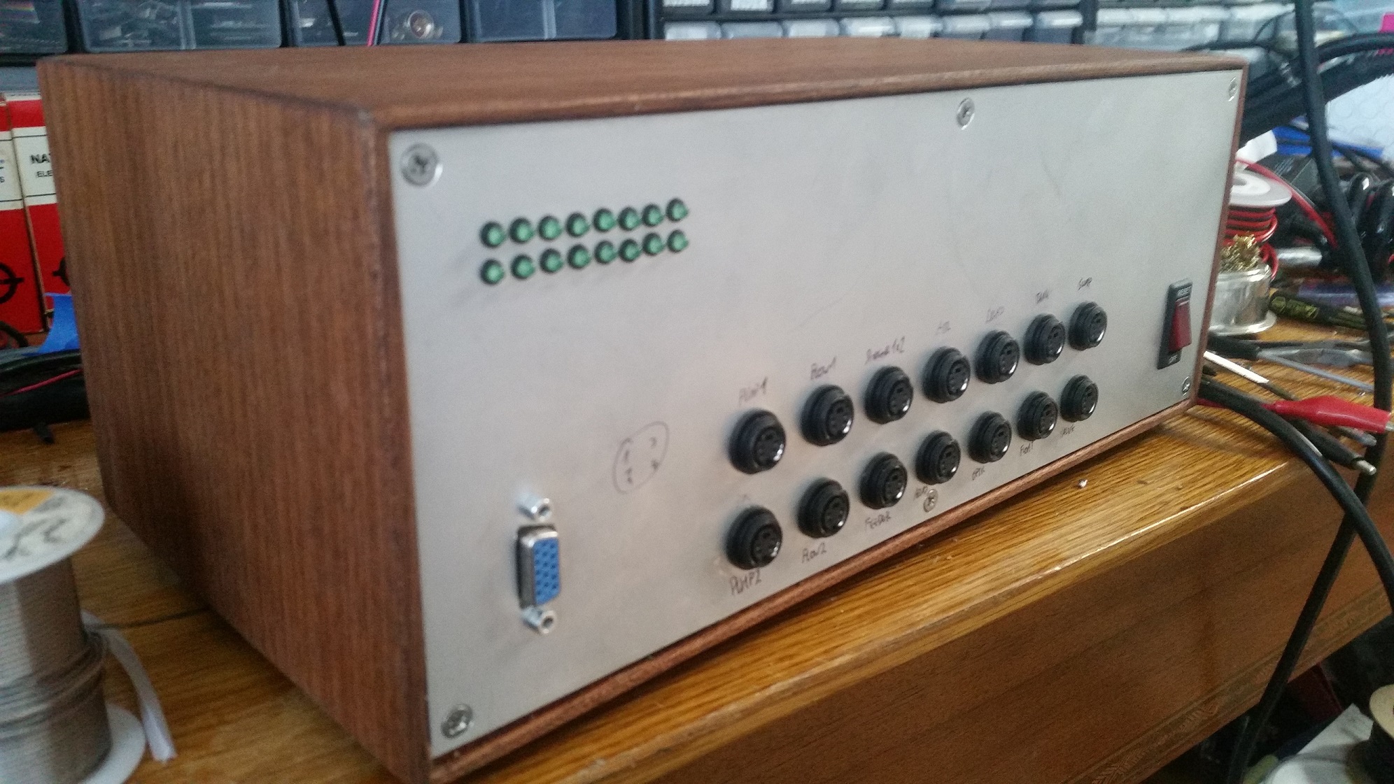
This is the front of the controller before stenciling. It has LEDs to show which outlets are running, ports for all required sensors, a power switch with integrated breaker and light, and output to the display. I converted it to VGA as it offers a more secure connection than ethernet.

The rear shows the outlets, ethernet and programming ports, SD slot, in addition to LED and doser connectors. Inside this case is a 250W power supply to run lights and pumps directly, in addition to MOVs and surge protection for the outlets. The vent holes are for a pair of cooling fans.

This is the current state of the aquarium. I welded a steel frame to support a 200 gallon tank, and built the cabinet and sump. Once I reinforce the floor, I can bring the tank itself up and start planting.
Most recently, I added magnetic stirrers. I did not want to sacrifice light channels, or run additional plugs to run them.
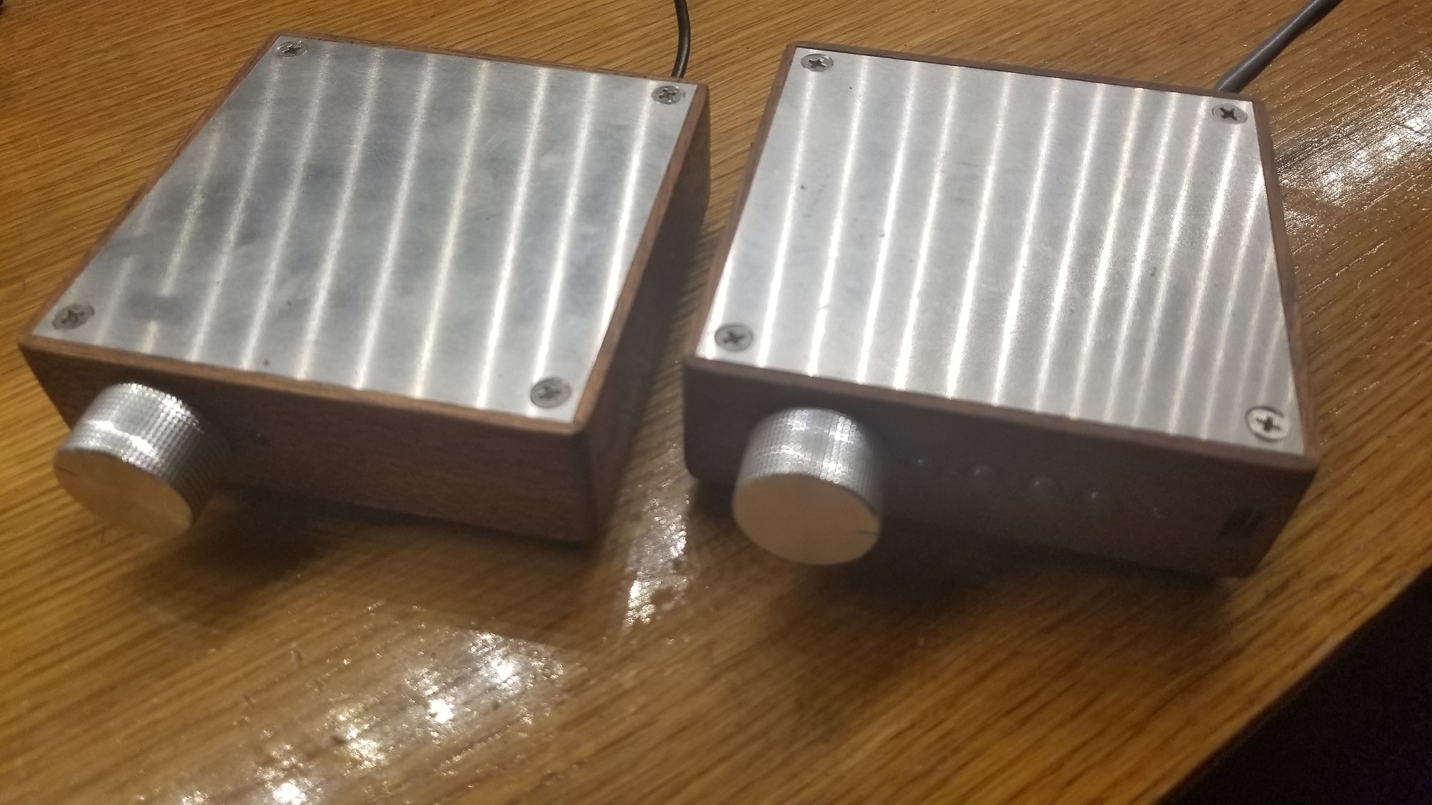
Instead, a master stirrer plugs into the doser port on the controller, and the doser then plugs into the stirrer. An onboard microcontroller records the pulse length when a doser is activated, and saves the value. It will then stir for a number of seconds, wait for the fluid to settle, then run the doser for the saved time and delete the value. RGB LEDs on the front display whether each channel is stirring, waiting, or dosing, and a rocker switch on the side enables or disables the stirring function. The power LED is bicolour, and will indicate whether or not the stirrers are enabled. The knob is a speed control.
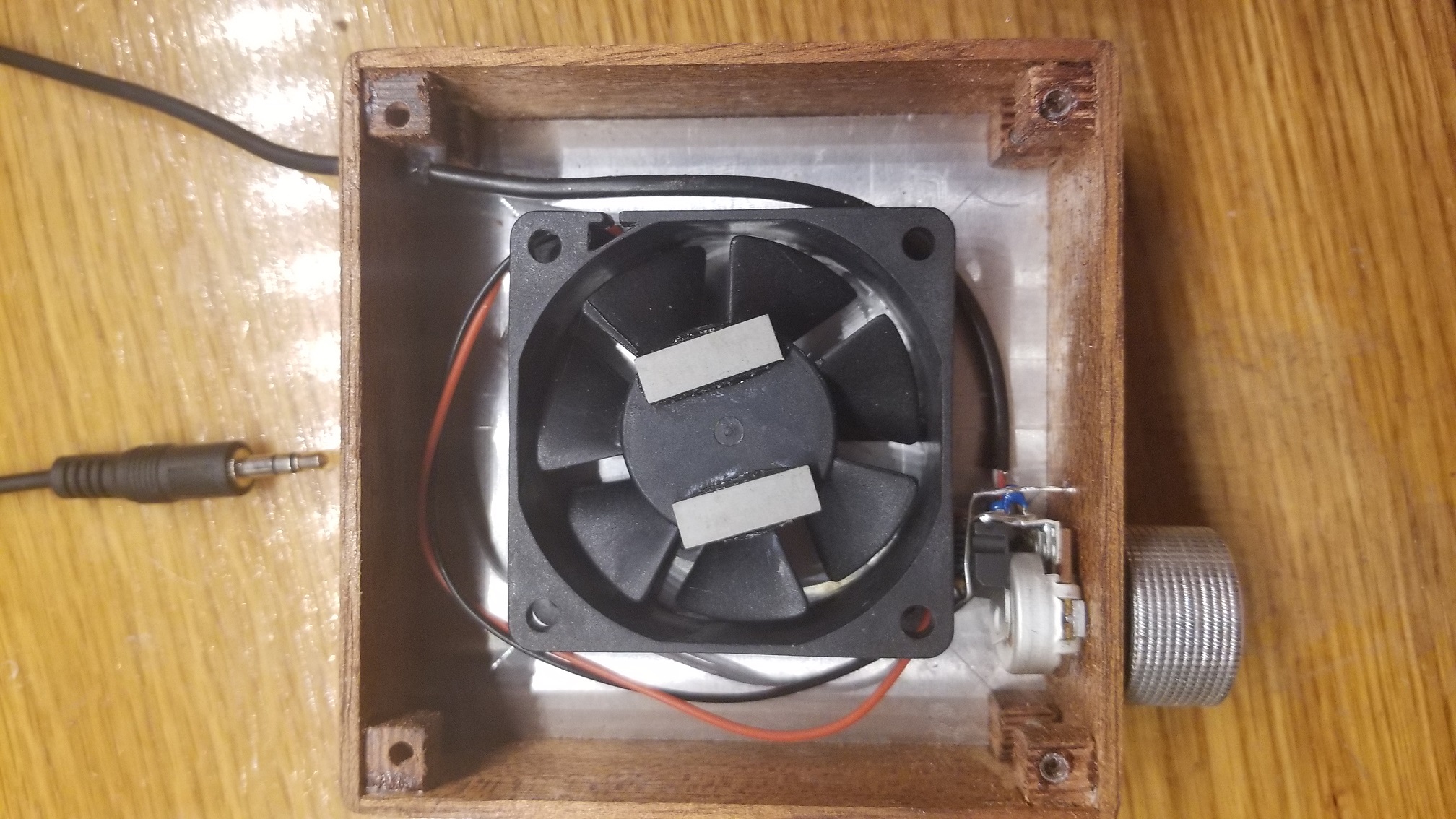
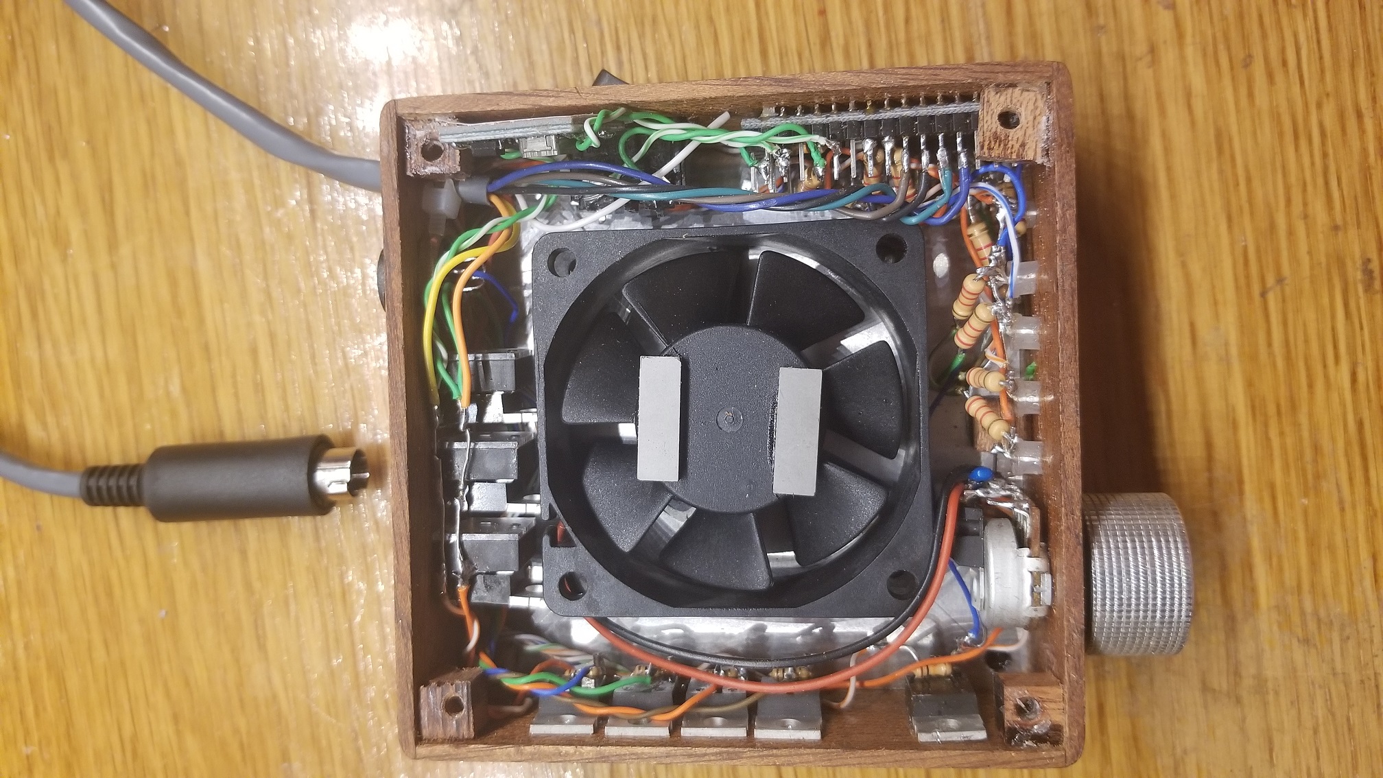
As you can see, the slaves are far simpler, containing only a fan and speed control.
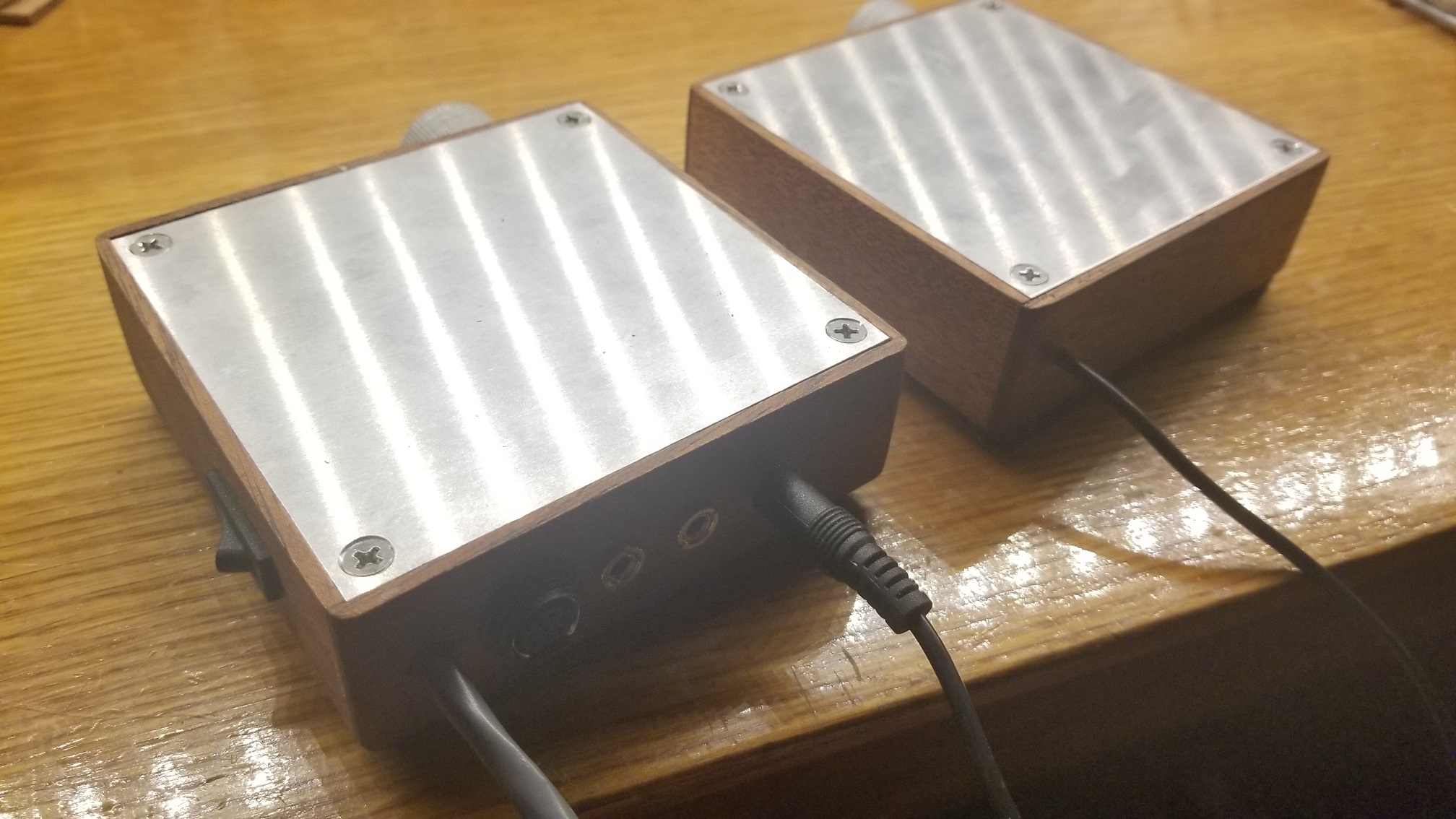
From the back, you can see the ports for three additional stirrers, and the connector for the dosing pumps.
I have many more pictures, notes, and features if there's any interest.
This is how I've set up my devices. I made mahogany and aluminium boxes, and moved everything to a single, self-contained case.
This is the front of the controller before stenciling. It has LEDs to show which outlets are running, ports for all required sensors, a power switch with integrated breaker and light, and output to the display. I converted it to VGA as it offers a more secure connection than ethernet.
The rear shows the outlets, ethernet and programming ports, SD slot, in addition to LED and doser connectors. Inside this case is a 250W power supply to run lights and pumps directly, in addition to MOVs and surge protection for the outlets. The vent holes are for a pair of cooling fans.
This is the current state of the aquarium. I welded a steel frame to support a 200 gallon tank, and built the cabinet and sump. Once I reinforce the floor, I can bring the tank itself up and start planting.
Most recently, I added magnetic stirrers. I did not want to sacrifice light channels, or run additional plugs to run them.
Instead, a master stirrer plugs into the doser port on the controller, and the doser then plugs into the stirrer. An onboard microcontroller records the pulse length when a doser is activated, and saves the value. It will then stir for a number of seconds, wait for the fluid to settle, then run the doser for the saved time and delete the value. RGB LEDs on the front display whether each channel is stirring, waiting, or dosing, and a rocker switch on the side enables or disables the stirring function. The power LED is bicolour, and will indicate whether or not the stirrers are enabled. The knob is a speed control.
As you can see, the slaves are far simpler, containing only a fan and speed control.
From the back, you can see the ports for three additional stirrers, and the connector for the dosing pumps.
I have many more pictures, notes, and features if there's any interest.


